Introduction
The original Sailor Hat for Raspberry Pi had some success as a marine embedded computer power supply and interface board, but the global semiconductor shortage has made it difficult to obtain the required components, and no boards have been manufactured since August 2021. Even though multiple interesting Raspberry Pi CM4 base boards have appeared during the past year, none have provided similar power management features as the SH-RPi. Due to frequent inquiries about the SH-RPi availability, I (Matti Airas) have decided to continue the development of the SH-RPi v2, which will be a completely redesign new version of the Sailor Hat for Raspberry Pi.
The SH-RPi v2 is a Hardware Add-on Top (HAT) for the Raspberry Pi that provides advanced power management features: wide 10-32V voltage-range input with current limiting, controlled shutdowns, uninterrupted power supply functionality for power glitches and voltage drops, as well as wake-up timers and hardware watchdog features, resetting the Raspberry Pi if the operating system crashes. The new version is a complete redesign of the original SH-RPi, and it is intended to be a more robust and reliable product, with a wider range of applications.
In contrast to the SH-RPi v1, the new board does not include an NMEA 2000 (CAN bus) interface. Instead, additional add-on boards such as the Waveshare Isolated CAN HAT or the Waveshare 2-CH RS485 HAT can be used to add NMEA 2000 or NMEA 0183 interfaces, respectively, to the Raspberry Pi. This configuration still allows powering a Raspberry Pi over the NMEA 2000 network, if desired.
Intended Use Cases
With the SH-RPi v2, a Raspberry Pi (or any other similar embedded computer) can be used as a generic appliance device. The power can be switched on and off, and the device will automatically shut down in a controlled manner when the power is switched off. Users don’t have to worry or even know about having to manually shut down the device, as it will be done automatically.
In addition to the original marine embedded computer use cases, the new device revision also excels in automotive applications, 3D printer control, digital signage, home automation, and many other applications where reliable and robust power supply and shutdown capabilities are required.
Features and Design Goals
Continuous input voltage range of 9-32 V allows for powering the device from a wide range of power sources, including automotive and marine 12 V and 24 V nominal systems, as well as regular 12 and 24 V power supplies.
Input current can be limited to 0.8 A, 2.0 A or 3.0 A. Without current limiting, the initial supercapacitor charging current could be large enough to overpower many power supplies or require impractically large fuse ratings and/or wire sizes. An 0.8 A current limit is suitable for most applications with regular 12V power supplies, and also allows for powering a Raspberry Pi via an NMEA 2000 interface. Higher current limit settings can be used for faster supercap charging at cold startups, and in automotive and marine applications when dedicated power wiring is available, or when exceptionally large steady output current is required.
SH-RPi voltage output is 5 V, with a current capability of up to 5 A. Continuous current capability is dependent on the input current limiting setting. Even on the 0.8 A input setting, high momentary currents can be supplied by the supercapacitor.
Power output can be supplied via the Raspberry Pi GPIO header, or via a separate 2.54 mm pitch screw terminal block.
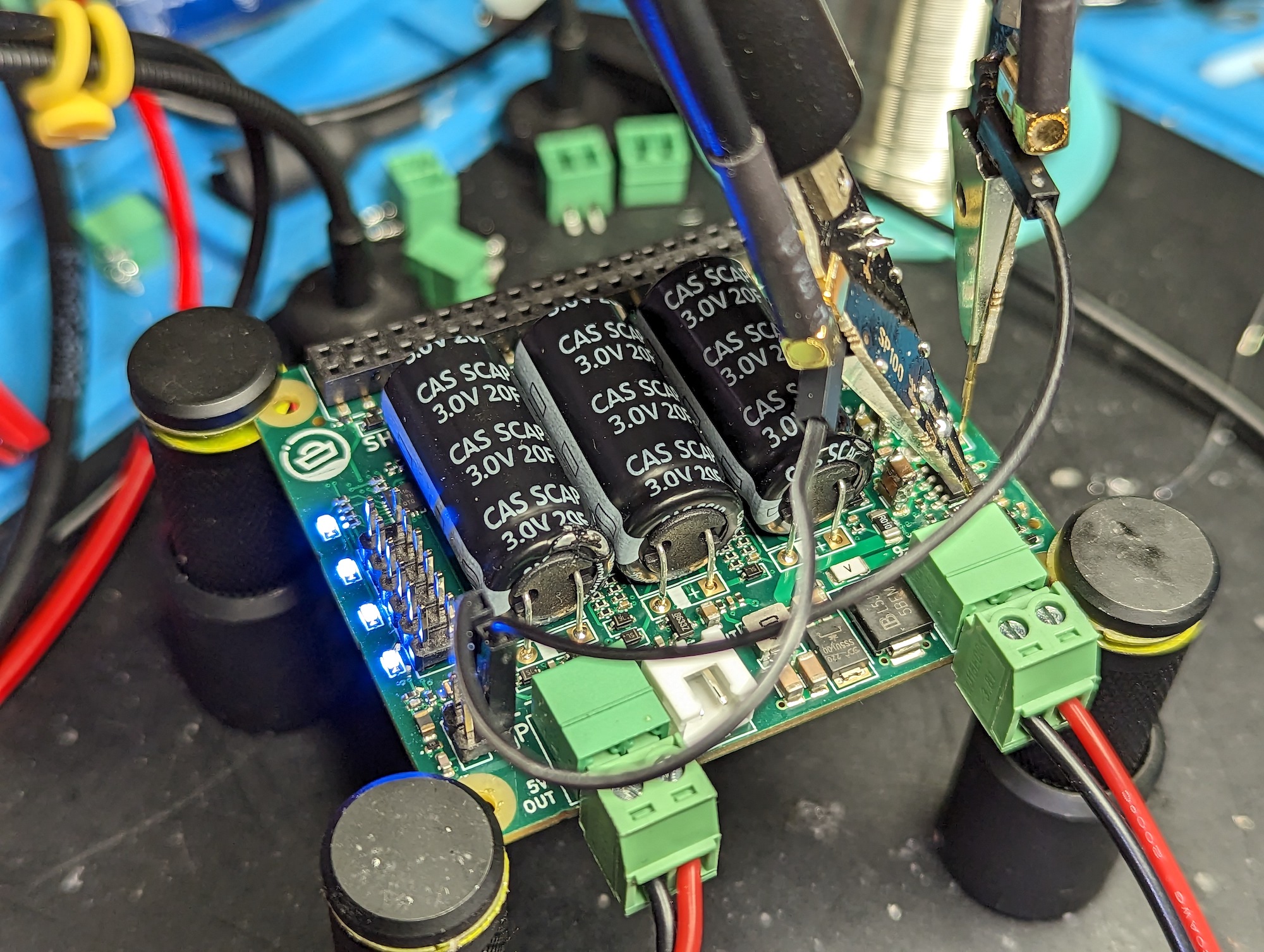
Three supercapacitors are used to provide uninterrupted power supply functionality for power glitches and voltage drops. They are able to provide last-gasp power for up to 30 s at 5 V and 1 A. This, together with the auxiliary service software, allows for safe shutdowns when the input power is cut off.
The power management logic is implemented in an Atmel ATtiny1616 microcontroller. The microcontroller is connected to the host computer using the I2C bus. It provides the host computer with input voltage and current measurements, as well as the supercapacitor voltage and other status information. The microcontroller also controls four LEDs that indicate the power supply status and charge state.
SH-RPi v2 includes an on-board real-time controller which can be used for accurate timekeeping while the Raspberry Pi is powered off. The RTC can also be used to start the Raspberry Pi at a specified time.
Additionally, there are two external input lines that can be used for external wake-up events or for attaching an external power button.
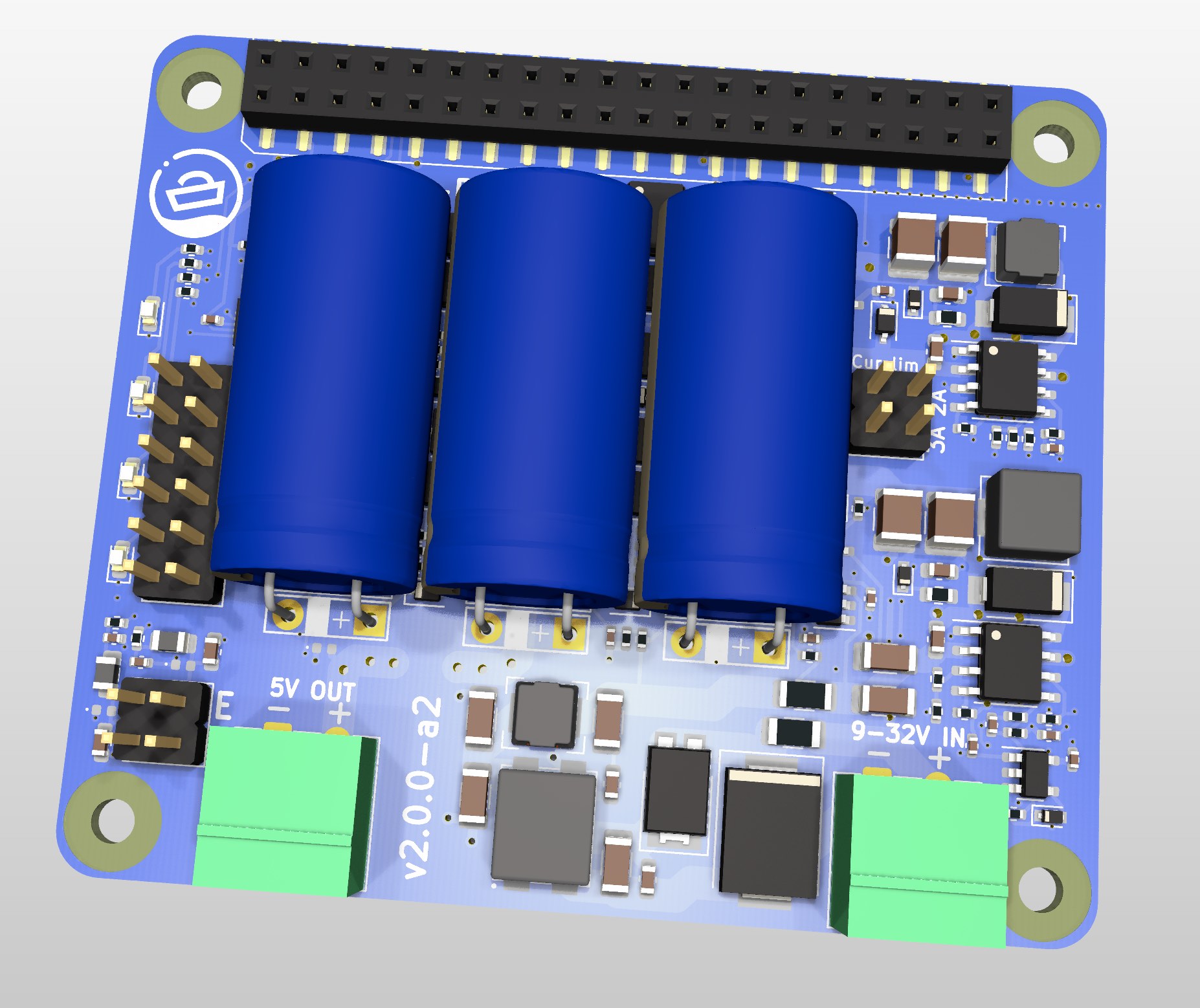
All of the above features are implemented in a compact HAT form factor, which allows for easy integration into existing Raspberry Pi based systems. Additional HATs can be stacked on top of the SH-RPi v2, for adding extra interfaces or other functionality.
Finally, even SH-RPi v2 has been designed to be used as a Raspberry Pi HAT, it is also possible to use it as a standalone board for non-Raspi use cases. In such use cases, output power is delivered using a screw terminal block. Communication with the host computer can be done using the I2C bus, or by simple digital signalling.
Current Status
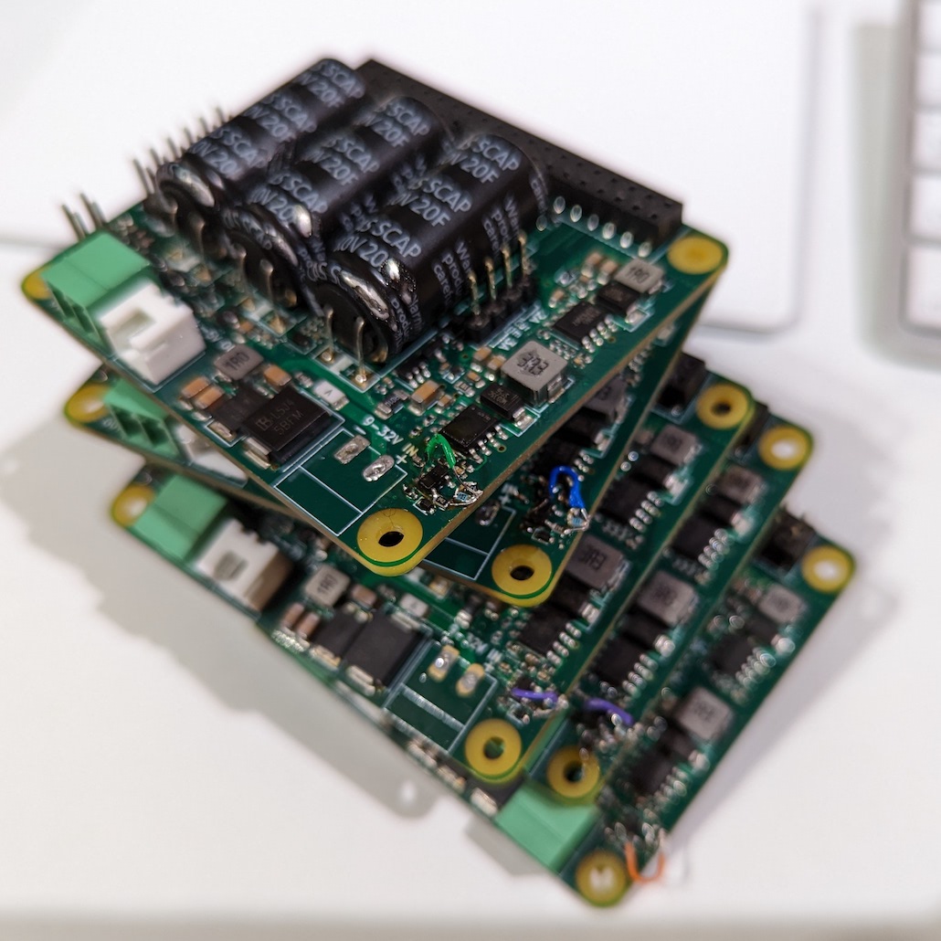
The initial board design was completed in October 2022, and the first 2.0.0-a1 prototype boards were received from the manufacturer in early November 2022.
Other than some trivial connector footprint design snafus, the board could be brought alive without major issues.
This allowed for adaptation of the existing SH-RPi v1 firmware to the new board, and for testing the basic functionality of the new board.
As things tend to go with analog electronics, the current limiting circuitry proved to be very difficult to get working reliably.
Either the limiting functionality was too weak, or the first step-down switching regulator was unstable and would oscillate.
Simulating switching regulator circuits is not trivial, and especially stability issues are difficult to predict.
In practice, a lot of trial and error and manual iteration was required to find suitable component values.
Given that the a1 design didn’t have facilities for easy component swapping, the repetitive process of replacing 0402 size (1.0 mm x 0.5 mm) lost its appeal quickly, to say the least!
Several weeks were spent in testing and debugging the current limiting circuitry, but persistence paid off, and the current limiting functionality is finally working reliably.
Initial EMI testing was also performed, and the results were very promising. A common-mode input filter was added to further reduce the EMI emissions. This necessitated the removal of the auxiliary 5 V output, which was not really needed anyway.
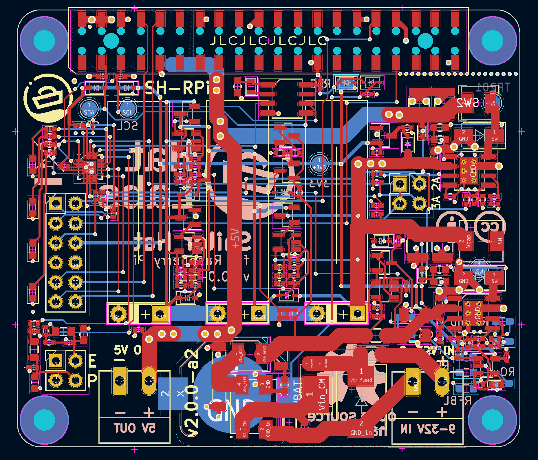
Additional test findings resulted in some minor design changes to the board, such as remapping of the ATtiny pins to allow for PWM output on all LED pins, and minor board layout changes, which resulted in an avalanche of trace rerouting.

The next proto version, 2.0.0-a2, is currently being finalized.
It will be manufactured with two different variants, one with the original RT6365 buco converter, and one with Texas Instruments’ LMR14050 converter, which is again available in smaller quantities.
The a2 boards have unpopulated larger component footprints on the bottom side of the board.
This allows for easier component swapping and final verification of the analog design.
Otherwise, the a2 boards should be feature-complete and hopefully identical to the final production boards.
Next Steps
The a2 board orders will be placed before the end of December 2022.
Once they arrived, typically within 14 days of the order, the boards will be tested again.
Full EMI pre-compliance testing will be performed, and the board will be further tested both in the lab and with actual Raspberry Pi hardware.
Once the a2 boards are deemed to be working, the final production board design will be finalized.
This will hopefully consist of only removing the test footprints. Then, the final production board design will be sent to the manufacturer for a small-scale production run.
Several other tasks remain to be done before the SH-RPi v2 can be sold. The Raspberry Pi software installation script needs to be updated to support the new board features. The SH-RPi daemon should also be updated to support inter-process communication, so that the board can be controlled using external software.
For QA purposes it is essential to have a test jig, which can be used to automatically test the manufactured boards. The test jig needs to test the current limiting and power output functionality, communication with the host computer, RTC functionality, and all external interfaces.
In large-scale production, design and manufacturing of the test jig can be a significant challenge and may take a lot of time. For Hat Labs designs with somewhat smaller production runs, good results can be achieved with 3D printed test fixtures, pogo pins and testing electronics built with a Raspberry Pi or an SH-ESP32, and simple bread-boarded circuits.
Some additional tasks include updating the online documentation and the quick start guide as well as preparing the packaging.
Timeline
My initial estimation was that the SH-RPi v2 would be ready for sale at the end of 2022. Obviously, this didn’t happen, partially due to the longer-than-expected testing and debugging time, but probably mostly due to over-optimistic initial estimates.
If no major issues are found in the a2 boards, I hope to have the SH-RPi v2 ready for sale in the first quarter of 2023. But no matter what, they will be ready before the beginning of the sailing season on the northern hemisphere!
Feedback
If you have any questions, comments or suggestions, please post them at the Hat Labs discussion board, or directly by email to matti.airas@hatlabs.fi!